
. INTRODUCTION
Trapped charge dating methods such as luminescence and electron spin resonance (ESR) are increasingly used for sediment dating. The physical phenomena that these methods rely upon are based on the presence of trapping states in the crystalline structure of the minerals used. The concentration of electrons and/or holes held in these metastable states increases with continuous excitation of the charge by the natural background radiation and can be used to estimate the time elapsed since the traps were emptied, based on the assumption that the dose rate remained constant during time.
The key event in sediment dating is the formation of a sediment layer, that is, the deposition of mineral grains after they have been transported by wind or water, and then covering with another layer. If any of the trapped charge methods are to be used for dating a sediment layer, the traps must be empty at the time of its formation, or the residual level must be known. The main natural factor responsible for trap emptying before grain deposition in the case of sediments is sunlight exposure, so only the traps which are sensitive to sunlight bleaching can be used for dating.
Two phenomena are exploited to measure the concentration of trapped charge when dating sediments: optically stimulated luminescence (OSL) and ESR. According to the current understanding of the OSL processes in the minerals commonly used for dating (quartz or potassium feldspars), OSL dating relies on the quantification of the concentration of trapped electrons (Bailey and Arnold, 2006; Preusser et al., 2009; Friedrich et. al., 2016; Peng and Pagonis, 2016). On the other hand, in the case of ESR applied on quartz both electron (such as Ti centres) as well as hole traps (Al-hole centres) are used in the so-called multiple centre (MC) approach (Toyoda, et al., 2000; Duval and Guilarte, 2015). These hole traps play the role of recombination centres in luminescence models of minerals. However, from both luminescence and ESR measurements it is known that the recombination centres are not completely emptied even after extremely long time of bleaching by light. When the sample is heated after the prolonged bleaching, the so-called residual thermoluminescence was reported by many (Singhivi et al., 1982; Smith and Rhodes, 1994; Spooner, 1994; Aitken, 1998; Chruścińska and Przegiętka, 2005; Przegiętka et al., 2005). Similar effects have been found in ESR measurements on hole centres (Walther and Zilles, 1994; Rink, 1997; Toyoda and Falguéres, 2003; Duval et al., 2017; Bartz et al., 2020). When the Al-hole centre is used for dating, it is common practice to quantify the residual concentration of holes; in other words, measuring the intensity of residual ESR signal after bleaching and subtracting it from the measured ESR for accurate equivalent dose determination (Voinchet et al., 2003). There are two approaches to estimate the residual ESR signal. The first is to measure it after exposure of many days to the sunlight simulator and express it as the percent of natural ESR signal measured without bleaching. The reported values vary between 40% and 80% (Walther and Zilles, 1994; Voinchet et al., 2003; Rink et al., 2007; Tsukamoto et al., 2017). Another way of residual ESR-level estimation is the measurement of a modern analogue or the reconstruction of the natural dose–response curves (i.e. the plot of intensity of the natural ESR signal versus the expected natural dose) using an extended sediment layer sequence for which an independent age control is available. The approximation of the residual signal is the intercept of the natural dose–response curve (Tsukamoto et al., 2018). However, these methods assume that the ESR residual level was the same for all samples in the stratigraphic sequence and can be practically carried out only under fortunate circumstances when age information is already available.
A recent study has shown that the residual level of the Al-hole ESR centre in quartz depends on the total absorbed dose (Timar-Gabor et al., 2020). This effect is in line with the simulation results performed for the kinetic model of charge transport processes involving two recombination centres and several types of traps which are populated and emptied with the participation of the conduction band. The key to this phenomenon is the presence of deep traps that are thermally stable and are not emptied by light, the so-called disconnected traps. The occupation of these traps by electrons after the bleaching dictates that the recombination centres are filled with an identical number of holes. Their number is shared between the different recombination centres adequately to the probability of electron recombination in the centres. For equal concentrations of the recombination centres, the residual level of holes is lower for the centre with the bigger recombination coefficient. The residual level of hole concentration in recombination centres after bleaching, that is, also the residual ESR signal corresponding to this centre, increases with the total absorbed dose until doses that cause the saturation of the electron population in the disconnected traps. As such, the residual signal depends on the concentrations of the deep disconnected traps and recombination centres as well as on their parameters.
Detailed results of the simulation of the processes leading to residual hole concentration (RHC) after optical bleaching are presented here for wide ranges of recombination centre parameters. The impact of the mutual relation of the parameters of individual recombination centres on the residual level of holes and the dependence of the residual level on dose is investigated. It is shown that for some ranges of parameters the function describing the changes in RHC level with dose does not simply increase up to the highest value at doses for which the disconnected traps are most populated by electrons, but it rises and then decreases again. This, on the one hand makes the level of the RHC hard to predict and on the other hand, can provide some insights into the relation between the parameters of recombination centres in the field of research on the properties of luminescent materials. It should be mentioned that the processes presented below, although investigated in close relation to the application of ESR signal of the aluminium hole centre in quartz for dating, generally apply to the occupation of recombination centres in insulating crystals in a metastable state. The effects observed in the simulations may explain the changes in luminescence effectiveness in phosphors after prolonged irradiation and exposure to light. The presence of deep disconnected traps can lead to surprising effects.
. METHODS
The simulations were performed by means of MATLAB differential equation solver ode15s, which is the appropriate tool for stiff equations. The charge transfer in the crystal was simulated for the (1) process of excitation – the filling of the traps and (2) the bleaching process.
The simulations were carried out for a kinetic model that includes four kinds of traps and two recombination centres (Fig. 1). Traps of the first kind are shallower than the others, are optically emptied during bleaching and are not thermally stable during irradiation. Traps of two other kinds are optically emptied during the bleaching and are thermally stable during irradiation and bleaching. The latter kinds of traps are deep and are neither optically nor thermally emptied in the simulated processes. They will hereafter be referred to as disconnected traps.
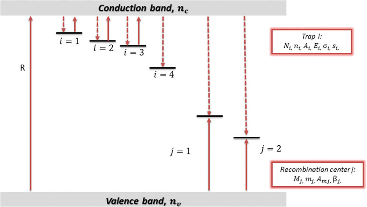
The kinetic equations solved at both steps of simulations are of the following form:
where ni (cm−3) and Ni (cm−3), i = 1 ... 4, are the concentrations of trapped electrons and the concentrations of traps, respectively, mj (cm−3) and Mj (cm−3), j = 1, 2, are the concentrations of holes trapped in recombination centres and the concentration of these centres, nc (cm−3) and mv (cm−3) are the concentrations of free electrons and holes in the conduction and valence bands, respectively, Ai (cm3 s−1), i = 1 ... 4, are the probability coefficients of electron trapping in the corresponding traps, Amj (cm3 s−1), j = 1, 2, are the probability coefficients of hole trapping in the adequate recombination centres, R (cm−3 s−1) is the intensity of the excitation irradiation producing the pairs of free electron and holes (taken as 1010 cm3 s−1 during the excitation process and 0 during bleaching) and βj (cm3 s−1) are the probability coefficients of a free electron recombining with a hole trapped in the corresponding recombination centre (hereafter referred to as recombination coefficient). The time-dependent probability of release of electrons from the i-th trap to the conduction band is equal γi = σi f, where σi (cm2) is the optical cross-section of i-th trap and f (cm−2 s−1) is the stimulation photon flux density (during excitation f = 0). The probability of thermal release of electrons from the i-th trap to conduction band is equal si exp (−Ei/kT), where Ei and si are the thermal depth and frequency factor of the i-th trap, respectively.The concentration N4 and the probability coefficient of electron trapping in disconnected traps A4, the concentrations of recombination centres Mj, the probability coefficient of a free electron recombining with a hole trapped in the luminescence centre βi, were changed to check their impact on the dependence of the residual level on the total dose which was previously absorbed. Unless otherwise specified, the parameters of the model used in simulations are as follows: N1 = 1.5 × 107 cm−3, N2 = 109 cm−3, N3 = 2.5 × 108 cm−3, N4 = 5 × 1010 cm−3, M1 = M2 = 1011 cm−3, A1 = 10−8 cm3s−1, A2 = 10−9 cm3 s−1, A3 = 5 × 10⁻¹⁰ cm3 s−1, A4 = 10−10 cm3 s−1, Am1 = Am2 = 10−9 cm3 s−1, β1 = β2 = 10−10 cm3 s−1, f = 1015 cm−2 s−1, σ1 = 1.96 × 10⁻¹⁵ cm2, σ2 = 2.22 × 10⁻¹⁷ cm2, σ3 = 5.41 × 10⁻¹⁸ cm2, E1 = 0.97 eV, E2 = 1.7 eV, E3 = 1.72 eV, s1 = 5 × 10¹² s−1, s2 = 5 × 10¹³ s−1, s3 = 5 × 10¹⁴ s−1, T = 293 K.
The model used in the simulations was constructed so that, while maintaining the greatest possible simplicity, it reproduces the degree of complication of the examined processes in real materials, especially in natural materials such as minerals. The values of individual parameters were taken from the work of Bailey (2001) on the model of luminescence in quartz. It should be emphasised that such parameters for quartz as recombination coefficients or centres of concentration are not strictly defined. What is more, in subsequent works presenting the model for quartz (Adamiec et al., 2004, 2006, 2008; Bailey and Arnold, 2006; Pagonis et al., 2014; Friedrich et al., 2017), their different values appear, allowing the correct reproduction of the effects observed in this material. Here, we selected one of many possible sets of centres’ parameters. In order to demonstrate the effects related to the dependence of RHC on the total absorbed dose, not so much the precise absolute values of these parameters are essential, but the mutual ratios of these values, especially the concentrations of centres and recombination coefficients. The particular values of both kinds of parameters can fluctuate from sample to sample because of the various crystal lattice defects present in the materials of different origins.
During simulations, the concentration of holes in both recombination centres m1 and m2 was monitored after optical bleaching. These values will be hereafter referred to as RHC. Their values were observed for different durations of irradiation with the intensity of the excitation (i.e. irradiation) producing pairs of free electrons and holes R equal to 1010 cm−3 s−1. Simulation results, for the sake of clarity of presentation, are shown in the form of dose dependence. The dose axis for all the results is directly related to the excitation time. It should be mentioned that several series of simulations were repeated for smaller R values, among them also values smaller by six orders of magnitude being chosen. When it can be assumed that one Gray generates about 1.5 × 10⁷ electron–hole pairs in 1 cm3 of quartz (Chen et al., 2020) the range of R value from 1010 cm−3 s−1 to 104 cm−3 s−1 corresponds to the dose rates ranging from 600 Gys−1 to 6 mGys−1. Such a range of dose rates was tested in the simulations and no differences in the shape of RHC dependency on the dose were found for various dose rates. At the initial step of the simulations, different times of bleaching were tested. The bleaching time of 1000 s was found to be sufficient to effectively depopulate the optically active traps and was used in all the further simulations. For the simulation results presented, the dependences of electron and hole concentrations on dose are shown for selected cases (panel a in the figures). They illustrate how the centres are filled during irradiation for various sets of model parameters.
. RESULTS
. Significance of the Presence of the Disconnected Trap
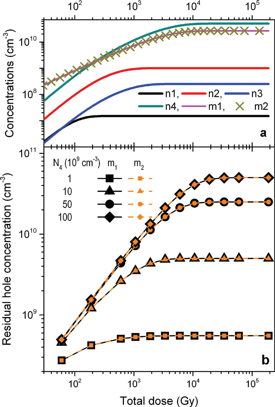
First the dependence of the RHC on the concentration, N4, and the coefficient of trapping probability, A4, of disconnected traps was investigated. For this purpose, the concentrations of recombination centres as well as their recombination coefficients were fixed and set equal for both centres, M1 = M2 and β1 = β2, respectively. It is intuitive to foresee that the greater the dose at which the saturation level of occupation of these traps is achieved the bigger is the dose at which the RHC in recombination centres after bleaching stabilises. Both parameters N4 and A4 control the rate at which the maximum filling of these traps is attained, so both are responsible for the shape of the dose dependence obtained for the residual hole concentration. The first parameter only determines the final saturation value of the RHC, because, as charge neutrality dictates, the number of holes trapped in both recombination centres is equal to the number of electrons in the disconnected traps. This is confirmed by the results presented in Fig. 2 that show the dependency of the RHC in both recombination centres after total emptying of shallower traps by optical stimulation for 1000 s for four different values of disconnected trap concentration N4 and the same A4 value. The RHC reaches its final saturation value for higher and higher doses as the concentration of disconnected traps increases.
Fig. 2
Results of simulations for recombination centres having equal concentrations (M1 = M2 = 1011 cm−3) and recombination coefficients (β1 = β2 = 10−10 cm3 s−1) for different values of the concentration of disconnected traps. (a) An example of growth curves for the electron and hole concentrations, respectively, in traps and recombination centres for the case when concentration of disconnected traps is N4 = 5 × 1010 cm−3; (b) The dependence of RHC after total emptying of shallower traps by optical stimulation for 1000 s on the total dose which was previously absorbed for four different values of N4. RHC, residual hole concentration.
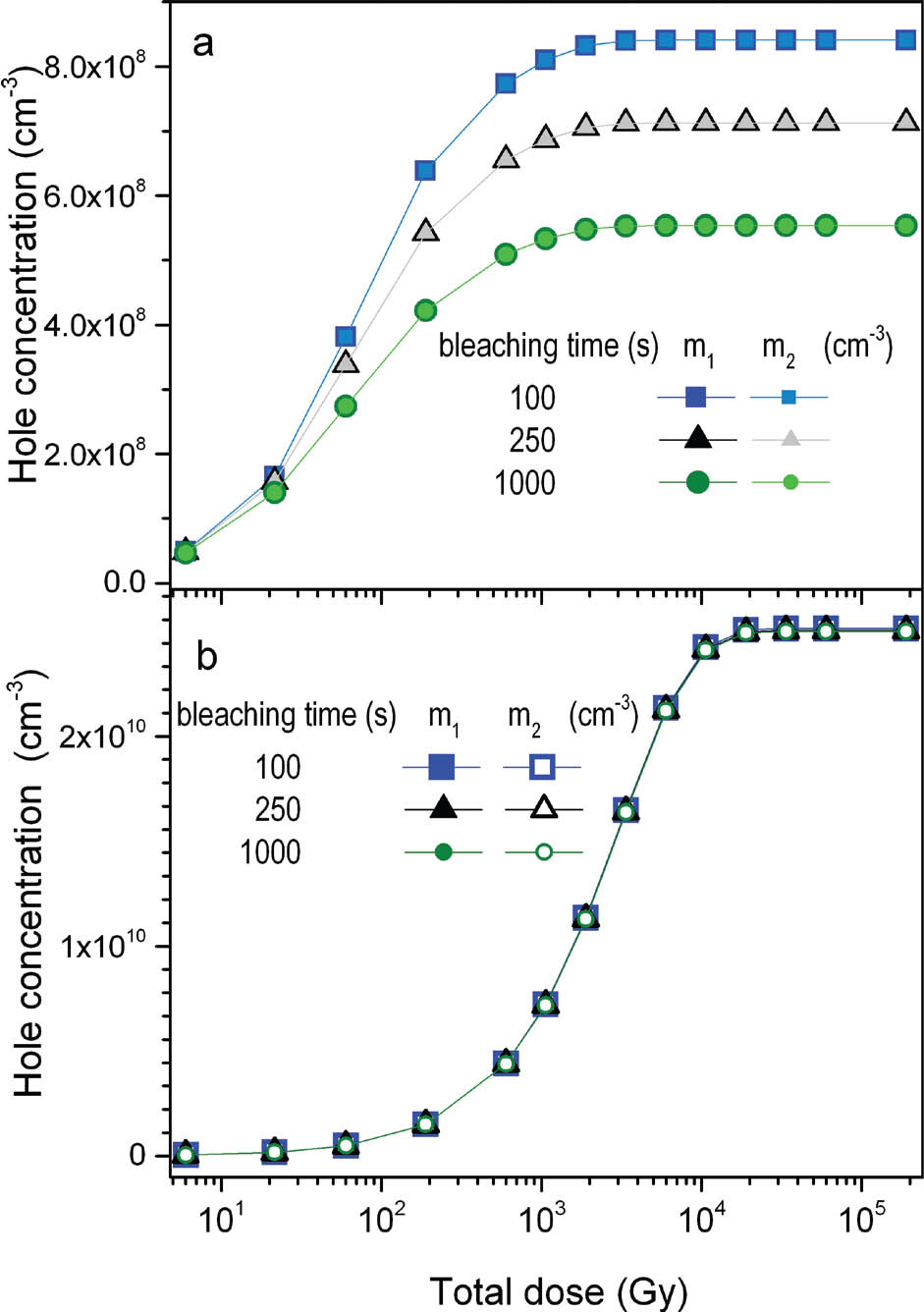
It is interesting to notice that the extent of changes of the concentration of holes in the recombination centres with the time of optical bleaching reflects the general relation of the concentration of optically active traps to the concentration of the disconnected traps. When the concentration of the latter has overwhelming majority over the concentration of bleachable traps, the differences between the hole concentrations for different bleaching times are hardly noticeable. This is illustrated in Fig. 3b. In Fig. 3a, the differences in the hole concentrations for various bleaching times can be clearly observed, because the concentration of the disconnected trap is comparable to the concentrations of optically emptied traps. Such observations can be used for a qualitative assessment of the proportion of the concentration of both kinds of traps.
Fig. 3
The dependence of hole concentrations in both the recombination centres (M1 = M2 = 1011 cm−3, β1 = β2 = 10−10 cm3 s−1) on the total dose for different times of bleaching and two different concentrations of disconnected traps are (a) N4 = 109 cm−3; (b) N4 = 5 × 1010 cm−3. The concentrations of optically active traps are N2 = 109 cm−3 and N3 = 2.5 × 108 cm−3.
For a defined concentration of disconnected traps, the coefficient of probability of electron trapping, A4, dictates the rate of filling these traps. Therefore, its influence on the dose characteristics of RHC is easy to predict. The saturation level for different values of A4, and fixed concentrations of the centres, stays the same but it is reached for progressively lower doses when A4 increases. Such an effect is illustrated in Fig. 4 that shows the changes in RHC level in the recombination centres with dose. When A4 is equal to 10−11 cm3 s−1, the RHC saturates for doses larger than 100 kGy, while for the trapping probability coefficient equal to 10−9 cm3 s−1 saturation starts around 5 kGy. Changes in the dose range for which the saturation of RHC occurs are dynamic when A4 is smaller than the trapping probability coefficients for the main optically active traps (A2 = 10−9 cm3 s−1, A3 = 5 × 10⁻¹⁰ cm3 s−1; see in Fig. 4b the curves for A4 = 0.1 × 10⁻¹⁰ cm3 s−1and 10−10 cm3 s−1). For the higher A4 values, comparable to A2 and A3, ranging from 10−10 cm3 s−1 to 10−9 cm3 s−1, the saturation range of RHC does not significantly change. It stabilises when A4 is comparable to the larger coefficient of the optically active traps, that is, in this case A2 = 10−9 cm3 s−1.
Fig. 4
Results of simulations for recombination centres having equal recombination coefficients (β1 = β2 = 10−10 cm3 s−1) and concentrations, respectively, M1 = 1011 cm−3 and M2 = 4 × 1010 cm−3, for different values of the coefficient of probability of electron trapping in disconnected traps A4. (a) An example of growth curves for the electron and hole concentrations in traps and recombination centres for the case when coefficient A4 = 10−10 cm3 s−1; (b) The dependence of RHC on the total dose which was previously absorbed for four different values of A4. The concentration of disconnected traps is set to N4 = 5 × 1010 cm−3. RHC, residual hole concentration.
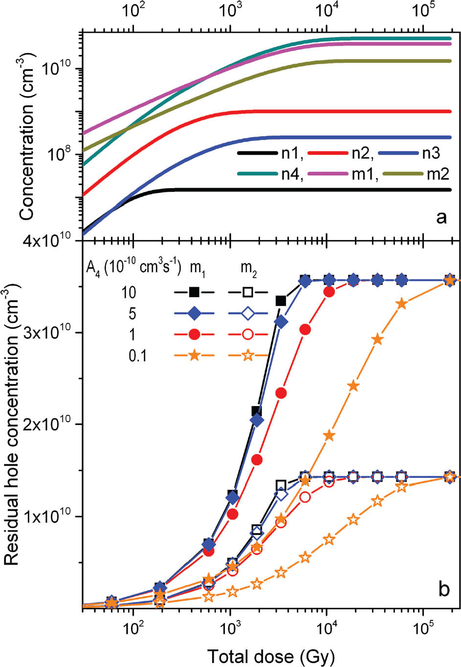
The simulations presented in Fig. 4 were made for different concentrations of recombination centres, M1 = 1011 cm−3 and M2 = 4 x 1010 cm−3. Such cases are considered in detail in subsection ‘The influence of the concentrations of the recombination centres on the RHC’. Here, it is used to demonstrate that the dose at which the residual level reaches its final saturation level does not depend on the mutual relation of recombination centre concentrations. The factors that control this are the parameters of disconnected traps N4 and A4.
. Influence of the Properties of Recombination Centres
As it can be clearly seen in Fig. 2, the maximum RHC as a function of the previous given dose depends on the relation of the concentration of disconnected traps N4 to the concentrations of recombination centres. However, Fig. 2 presents simulation results for an exceptional case when both recombination centres have the same concentrations (M1 = M2) and recombination coefficients (β1 = β2). While for different samples of the same material the concentrations of specific defects (here M1 and M2) may be different, the recombination coefficients of these defects (here β1 and β2) remain constant from sample to sample. When one knows the recombination coefficient values of specific centres in the crystal, which is not the case with quartz, changes in RHC may be considered only regarding to different concentrations of recombination centres. So, it is interesting to observe how these different parameters individually affect the RHCs in recombination centres.
. The impact of recombination coefficients of the centres on the RHC
First, the simulation was conducted for equal concentrations M1 and M2 and different relations between the recombination coefficients β1 and β2 were tested with the fixed assumption that β1 > β2. An interesting effect can be noticed in Fig. 5, which shows the results for a wide range of β2 values and β1 equal to 10−10 cm3 s−1. When β1 is greater than β2 but no more than four times (5 × 10⁻¹¹, 7.5 × 10⁻¹¹ cm3 s−1) the dependence of the RHC on dose is similar in shape to all the curves presented previously in Figs. 2–5. For lower β2 values (in Fig. 5 for β2 = 0.5 × 10⁻¹¹, 10−11, 2.5 × 10⁻¹¹ cm3 s−1), in the case of the recombination centre number 1 with the greater recombination coefficient β1, a peak is observed before the dependence of RHC on dose reaches its stable final level. The amplitude of this peak depends on the relationship between the concentrations of recombination centres M1 and M2 which will be shown in subsection ‘The influence of the concentrations of the recombination centres on the RHC’. The ratio β1/β2, instead, decides about the final saturation value of the RHC for doses higher that those causing the peak. For a fixed M1/M2 ratio, the level is the lower the greater the difference between the two coefficients and reaches 0 for extreme cases, here for β1/β2 = 20.
Fig. 5
Results of simulations for recombination centres having equal concentrations (M1 = M2 = 1011 cm−3) and different values of the recombination coefficients β1 and β2. β1 is fixed and equal to 10−10 cm3 s−1, when β2 is changed. (a) An example of growth curves for the electron and hole concentrations in traps and recombination centres for the case when the recombination coefficient β2 = 10−11 cm3 s−1. (b) The dependence of RHC on the total dose which was previously absorbed for five different values of β2. The concentration of disconnected traps is set at N4 = 5 × 1010 cm−3. RHC, residual hole concentration.
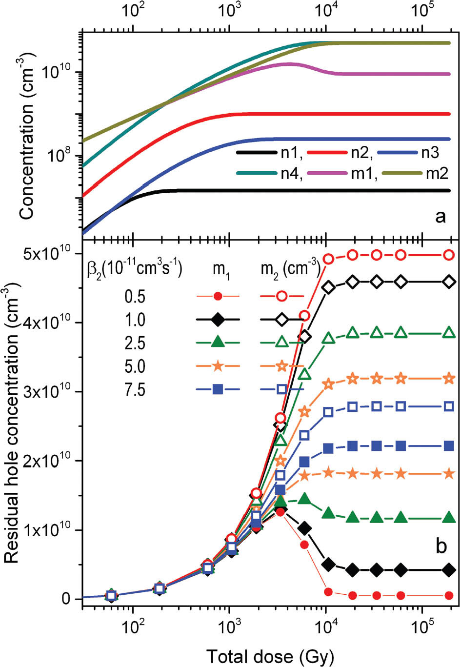
It is important to notice that the peak similar to that observed in the dependence of RHC on the total dose appears also in the growth curves of hole concentration of the respective recombination centre (see Fig. 5a). This is a consequence of the fact that the recombination rate is controlled not only by the recombination coefficient (β1 and β2) but also by the current hole concentration m1 and m2. The terms in the kinetic equations responsible for recombination rates are β1m1nc and β2m2nc, which show that both processes are also coupled by the current state of electron concentration in the conduction band described by Eq. (3) and compete with each other. For low β2 and m2, the rate of recombination at centre 2 is simply lower than at centre 1, which although catches the holes during irradiation simultaneously it loses them more effectively. When all the traps are almost full, the electrons in the conduction band are less effectively trapped and then the recombination process at centre 1 becomes the most effective way for their relaxation. That leads to lower hole concentration in this recombination centre after irradiation and then also to the lower RHC values after bleaching.
The value of β1/β2 ratio for which the peak in the dose dependence of RHC appears is controlled by the relation of recombination centres concentrations M1 and M2 to the concentration of disconnected traps. When both M1 and M2 are significantly bigger than N4 the peak is always observed for β1 > 2β2. For close values of the concentrations of recombination centres and disconnected traps the difference between β1 and β2 has to be bigger. The effect is illustrated in Fig. 6, which is a repetition of the simulations presented in Fig. 5 but with two different concentrations of recombination centres M1 and M2. In Fig. 6a and b M1 = M2 and is twice that of the values chosen in Fig. 5, while in Fig. 6c and d the value is a much smaller and equal to N4. As can be seen, for example, for β2 = 10−11 or 2.5 × 10⁻¹¹ cm3 s−1 in Fig. 6a, the final saturation value, in other words the stabilisation level for the RHC is clearly lower for bigger M1 and M2 (equal to 2 × 1011 cm−3) and for β2 = 5 × 10⁻¹¹ cm3 s−1 the slight decrease after approaching the maximum value of hole concentration may be noticed. The latter was not present for lower M1 and M2 (1011 cm−3) in Fig. 5. When M1 and M2 are close to the concentration of disconnected traps (Fig. 6c, all equal to 5 × 1010 cm−3), the decrease in the dose dependence curve after reaching the maximum value can be hardly noticed for β2 = 2.5 × 10⁻¹¹ cm3 s−1, for which the decrease is clearly visible in Fig. 5. The very low value of final saturation value, close to 0, seen for the smaller value of β2 (0.5 × 10⁻¹¹ cm3 s−1) in Figs. 5 and 6b is not observed here.
Fig. 6
Results of simulations for recombination centres having equal concentrations and different values of recombination coefficients β1 and β2. β1 is fixed and equal to 10−10 cm3 s−1, when β2 is changed. (a) Example of growth curves for the electron and hole concentrations in traps and recombination centres for the case when their concentrations are M1 = M2 = 2 × 1011 cm−3 and recombination coefficient β2 = 5 × 10⁻¹⁰ cm3 s1. (b) The dependence of RHC on the total dose which was previously absorbed for five different values of β2 when M1 = M2 = 2 × 1011 cm−3. (c) Example of growth curves for the electron and hole concentrations in traps and recombination centres for the case when their concentrations are M1 = M2 = 5× 1010 cm−3 and recombination coefficient β2 = 10−11 cm3 s−1. (d) The dependence of RHC on the total dose for five different values of β2 when M1 = M2 = 5 × 1010 cm−3. The concentration of disconnected traps is N4 = 5 × 1010 cm−3. RHC, residual hole concentration.
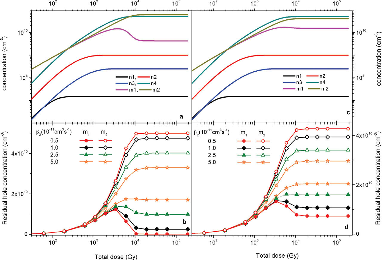
It is also worth noting that the amplitudes of the peaks observed in the dose dependence curves presented in Figs. 5 and 6 do not change. Additionally, it was checked that as long as the M1/M2 ratio does not change, the concentrations M1 and M2 alone have no effect on the peak height of the dose dependence of the residual hole centres. A corresponding result of the simulations is presented in Fig. S1 in Supplementary Materials. This is because, as was mentioned above, it is the M1/M2 ratio that dictates the amplitude of the peak. Here, it can be also observed that in the case when M1 and M2 are smaller than N4 the peak in the dose dependence curve is not observed (Fig. S1 in Supplementary Materials, curve for M1 = M2 = 2.5 × 1010 cm−3).
. The influence of the concentrations of the recombination centres on the RHC
To investigate the influence of the concentration of the recombination centres on the changes in RHCs with dose, the β1/β2 ratio and the concentration of disconnected traps N4 were established and the processes were modelled for different relationships between M1 and M2. Fig. 7 shows the RHCs after emptying the optically sensitive traps versus the dose. As the β1/β2 ratio is set to 10 the peak can be observed for every case. The greater the M1/M2 ratio the higher is the peak in the dose dependence for the recombination centre 1. It was checked that for fixed M1/M2 ratio the individual values of recombination centre concentrations here play a minor role. The results illustrating this are shown in Fig. S2 in the Supplementary Materials.
Fig. 7
Results of simulations for recombination centres for fixed recombination coefficients: β1 = 10−10 cm3 s−1, β2 = 10−11 cm3 s−1 and various ratios of the recombination centre concentrations M1/M2. M1 is always equal to 1011 cm−3 and the value of M2 is changed; N4 = 5 × 1010 cm−3. (a) Example of growth curves for the electron and hole concentrations in traps and recombination centres for the case when the recombination centre concentration is M2 = 5 × 1011 cm−3. (b) The dependence of RHC on the total dose which was previously absorbed for five different values of M2. RHC, residual hole concentration.
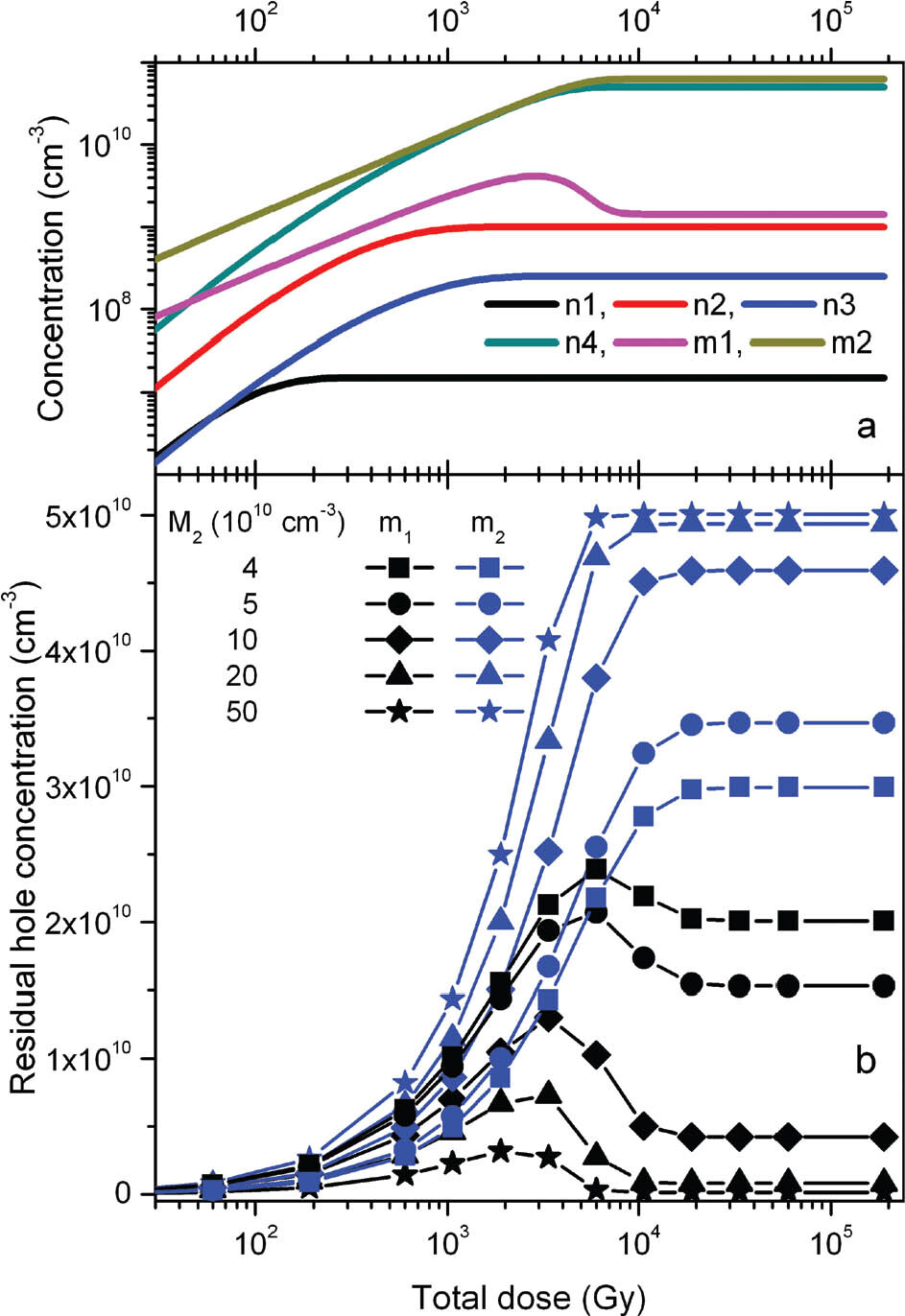
In Fig. 7, an interesting detail can be noticed. The stabilisation level of RHC is attained for lower doses when concentration M2 increases. This indicates that not only the concentration of disconnected traps dictates the dose range where RHC stabilisation occurs but also, in the second order, its relation to the sum of concentrations of recombination centres (M1 + M2).
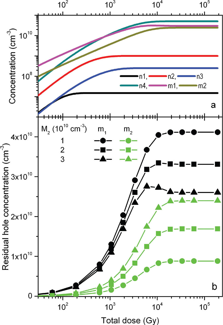
As it was already noticed above, the peak in the dose dependence of the RHC does not occur when M1 = M2 < N4. However, when only one of the recombination centres has the concentration lower than N4, the peak appears. A good example is the dose dependence shown in Fig. 7 for M2 = 4 × 1010 cm−3. But it was also observed that for a small enough concentration of M2, the peak in the dose dependency curve disappears and additionally the relation between the final saturation values of RHC of both centres is changed. When for larger M2, the RHCs for recombination centre 2 saturates for larger values than for recombination centre 1, for very small M2 this is reversed, and the bigger saturation value is observed for centre 1. Both effects are presented in Fig. 8 for various M2 values. For very low M2, the hole trapping at this centre is very slow and because of that the hole concentration in this centre is continuously lower than the hole concentration in centre 1, which can be observed for both the hole concentrations during irradiation as well as RHCs in Fig. 8. This makes the recombination centre 2 ‘hardly visible’ for the processes taking place at centre 1 and unable to compete effectively. This makes the peak in the dose dependence curves, which is a result of competition between the recombination processes in both centres, vanishing with decreasing M2 values. When the dose range for which the stabilisation of residual levels occurs is reached, recombination centre 2 stays completely filled out after bleaching and centre 1 ensures fulfilment of the electric charge neutrality.
Fig. 8
Result of simulations for recombination centres for selected cases when the concentration M2 of recombination centre with the lower recombination coefficient is smaller than the concentration of the disconnected traps N4 = 5 × 1010 cm−3. The recombination coefficients: β1 = 10−10 cm3 s−1, β2 = 10−11 cm3 s−1 and the concentration M1 = 1011 cm−3. (a) Example of growth curves for the electron and hole concentrations in traps and recombination centres for the case when the recombination centre concentration is M2 = 3 × 1010 cm−3. (b) The dependence of RHC on the total dose for three different values of M2. RHC, residual hole concentration.
. DISCUSSION
ESR is a very powerful experimental tool for detection and identification of defects in solid states (Lund and Shiotani, 2014). As such, it is also a perfect tool for measuring the trapped charge concentration based on which ages are determined in ESR dating (Grün, 2020; Rizal et al, 2020). However, for accurate applications to be carried out the initial concentration of charge at the moment that is considered as the starting point for time measurement needs to be known. The most convenient and desirable situation is the lack of charge in the traps at this initial moment. The complexity of charge transport processes in crystals, and especially in natural crystals, makes one doubt that this state is always possible, especially when the ESR signal is reset by light exposure. When the measurement of such initial concentration gives a negligible result in comparison to the concentrations measured to determine the age, this assumption is likely valid.
For Al-hole signals, however, it is well known that this is not the case, and generally a value which is not negligible is determined and taken into account in the age estimation by adequately reducing the value obtained by the application of dating protocols (e.g. Voinchet et al., 2003). There is, however, one necessary condition for such corrections to be valid, and that is, the residual value obtained by laboratory measurements has to agree with the initial natural value at the start point for time measurement. The results presented here clearly show that this cannot usually be the case when the concentration of holes in recombination centres is used for age estimation and the factor responsible for the ESR signal zeroing is light. The ESR measurement results for quartz extracted from sediments clearly presented that the residual level of the ESR signal related to Al centre in quartz depends on the total dose absorbed in quartz before bleaching (Timar-Gabor et al., 2020). The nature of this dependence is a consequence of the rule of electric charge neutrality and the complex processes of charge transfer in the crystal. These processes are controlled by the physical parameters of the centres involved: the probability coefficients of electron or hole trapping in the corresponding trap and the recombination coefficients of a free electron recombination with a hole trapped in the recombination centre, as well as by the concentrations of the centres which are expected to vary from sample to sample.
We have investigated these effects using the band gap model by considering four electron traps and two recombination centres. It should be noted that although only one kind of disconnected trap type was considered, it stands for the many kinds typically found in quartz. The sum of their concentrations may well exceed the concentration of the optically emptied traps. The presented results seem to indicate a favourable case, which could allow the use of ESR signal from the Al-hole centre in quartz for sediment dating without the risk that the RHC level included in the age calculation does not correspond to the real one. It is when the concentration of disconnected traps is low compared with the concentration of optically emptied traps, as this makes the overall RHC levels low compared with the hole concentration in recombination centres immediately after excitation. In this case the difference between the ESR intensity of the natural sample at the moment of bleaching and that of the laboratory bleached sample will be negligible. Another case that may also lead to the same small values of the difference between the ESR intensity of Al-hole centre of the natural sample and that of the laboratory bleached one is quartz containing a recombination centre with a much higher concentration and a several times lower recombination coefficient than the Al-hole centre. Then the RHC for a centre of low concentration (here by assumption Al-hole centre) has mostly low levels and stabilises at a value close to 0. Such a case is illustrated by the dose dependence curves presented in Fig. 7 for M2 = 2 × 1011 cm−3 or 5 × 1011 cm−3. The concentration of centre 1 is M1 = 1011 cm−3, which is, two or five times lesser than the concentration of centre 2. Other similar cases are presented in Fig. S2 in the Supplementary Materials. However, it is hard to assume that the Al-hole centre plays the role of centre 1 in such cases, because it is very unlikely that there will be a centre in quartz having a higher concentration. Other ions occur in quartz in concentrations on average 10 times lower than Al. The latter occurs in high concentrations (up to a few 1000 ppm; Müller et al., 2003, 2012) due to the common occurrence of Al in the Earth’s crust and the similarity of ionic radius of Si4+ and Al3+. Because of the above, Al may be regarded as the recombination centre with potentially the highest concentration. In this case significant and variable RHCs can be expected for the Al-hole centre. This seems to be confirmed with practice, as usually high values are reported in the literature for the relative difference between the ESR intensity of the natural sample used for equivalent dose determination and that of the signal after laboratory bleaching of the natural samples in the laboratory. For example, Walther and Zilles (1994) reported a residual level at 44% of the natural, Voincet et al. (2003) reported a maximum bleached value of 50% of the natural, Rink et al. (2007) observed that the remaining signal was 56% of the natural ESR intensity measured prior to light exposure, while Voinchet et al. (2015) examined modern samples from various sedimentary environments (fluvial, marine and aeolian) and reported bleaching rates (expressed as percentage of the total signal that can be bleached) of up to 22%.
Due to the lack of data on the recombination coefficient of Al-hole centre, two opposite cases should be taken into account: (1) when this coefficient is bigger than for other centres and (2) when another centre with a bigger recombination coefficient than the Al-hole centre exists.
In the first case, complex dose dependence for the RHC after bleaching may be expected. The possible changes in the RHC with dose can be seen in Fig. 6 for different ratios of the probability coefficients of both centres and two different relations of the recombination centre concentrations to the disconnected trap concentration. The Al-hole centre plays here the role of centre 1. The shape of dose dependency curves for this centre (m1) varies between a function which monotonically increases up to a stabilisation level and a peak shape curve. The relative fluctuations in RHC with the total dose are the most significant for big differences between recombination coefficients (e.g. curves for β2 = 2.5 × 10⁻¹¹ cm3 s−1 and 5 × 10⁻¹¹ cm3 s−1, when β2 = 10−10 cm3 s−1), because after the peak very low values are reached in the stabilisation range. So a very low RHC observed for old samples could find explanation by the conceivable large predominance of the recombination coefficient of Al centre over the coefficients of the rest of the recombination centres. It may also explain why in some cases the results obtained by signals from the Ti and Al-hole centres in the quartz are consistent (Tissoux, et al., 2007, Bartz et al., 2018, 2020; Bahain et al., 2020; Duval et al., 2020), and in others they are not (Duval and Guilarte, 2015; Duval et al., 2017; Demuro et al., 2020). Sometimes the RHC for the Al centre is close to 0 (Tissoux, et al., 2012). However, such a case does not necessarily mean that the ESR signal of the Al-hole centre was also close to 0 as a result of bleaching during the deposition process of the quartz grains. In the case when the Al-hole centre has the biggest recombination coefficient from all centres, significantly higher RHC could appear for lower total absorbed doses (e.g. Fig. 7, curve for β2 = 10−11 and 5 × 10⁻¹² cm3 s−1). At this point, it is important to note that the complex peak shape is observed also in the growth curves of the hole concentration in recombination centres with the high recombination coefficient. This can be seen in Figs. 5(a)–7(a). The second case, when another centre has the bigger recombination coefficient than Al-hole centre, does not lead to as much complex behaviour of the dose dependence curve for the RHC. But still, the RHC changes with dose. The absolute value of the RHC strongly depends on the concentration and the probability coefficient of trapping of disconnected traps as can be observed in Figs. 2 and 4. Moreover, the same factors dictate the dose range where the RHC starts to stabilise. Therefore, also in the case when the Al-hole centre is not the recombination centre with the larger value of recombination coefficient, the dose dependence of the RHC may explain a variety of unbleachable residuals levels of ESR signal from the Al-hole centre reported in the literature as well the observed strong sample dependency (e.g. Toyoda et al., 2000, Tissoux et al., 2012; Duval et al., 2017, Bartz et al., 2020).
To sum up, regardless of the magnitude of the recombination coefficient of Al-hole centre, the residual concentration level of holes that is reached after bleaching of the quartz grains is practically impossible to estimate. The first reason is that the total dose of radiation absorbed by the grains since their inception, more precisely from the moment when the disconnected traps were emptied, to the moment when grains were exposed to light, is not known. The equivalent dose, the dose accrued after deposition until the moment of measurement, is obviously not known as this is the measurable in the dating process. For this reason, even if the dose dependency of RHC could be well constrained by laboratory experiments, it is not possible to determine where on this dose dependency the point of sediment deposition lies. The construction of natural dose response curves does not seem to fully solve the problem either, as one can easily see from the results above that it cannot be assumed that the RHC level was the same in all the samples used to construct the curve. The dose dependence of the RHC is sample specific because it strongly depends on the concentration of all kinds of defects in quartz.
. CONCLUSIONS
As long as the hole centres are believed to be disintegrated by light in the process of recombination of electrons from conduction band with holes in these centres, there is no reason to believe that the number of the residual hole centres that remain after the optical bleaching can be assumed to be constant and fixed from sample to sample. The detailed investigation of the possible levels of RHCs in recombination centres after bleaching shows that they change with the total dose absorbed in the history of the sample. The character of the dose dependence may vary significantly from sample to sample. It is hard to reconstruct the shape of this dependence, and it is impossible to know the total dose accrued in the crystal before the bleaching event. Until one knows the relation of the recombination coefficient of the centre whose signal is used for dating (in the case of quartz is the Al-hole centre) to the recombination coefficients of the other recombination centres, one cannot assume that the RHC determined in the laboratory corresponds to the natural value.